Skip to content

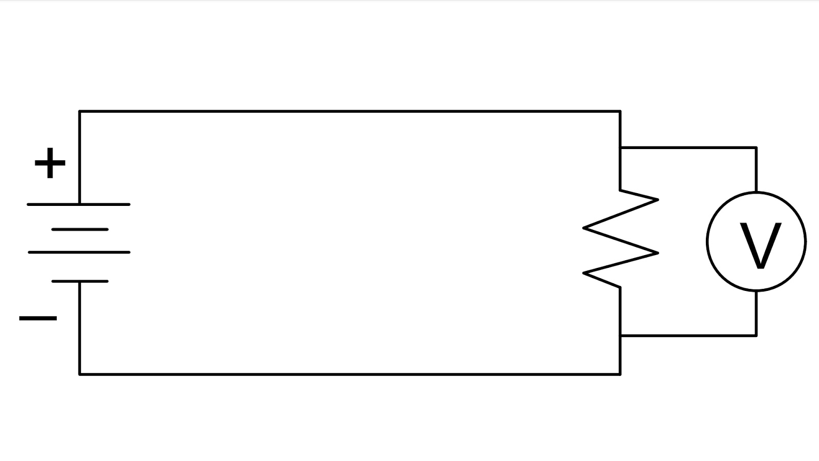
Voltmeter In A Series Circuit

Finding the Reading on a Voltmeter with Internal Resistance in a

Voltmeter diagrams britannica ammeter Voltmeter resistance voltage measurement Circuit diagram with voltmeter

Finding the Reading on a Voltmeter with Internal Resistance in a

Lesson video: design of the voltmeter A voltmeter is always connected in ……. in the circuit to measure the Why voltmeter connected in parallel with circuit {हिंदी}

Electrical meters

Measuring voltage with different voltmeters in parallelVoltmeter measure Series circuits: voltmeter readings in a series circuitDigital circuit voltmeter icl7107 using simple diagram meter dc pcb completely voltage figure negative eleccircuit.

Difference between ammeter & voltmeter (with comparison chartParallel voltmeter ammeter In the circuit shown here, the readings of the ammeter and voltmeterNcert q5.

Measuring voltage with different voltmeters in parallel - influences

Ammeter vs voltmeter

Ammeter circuit current voltmeter difference between ampere simple should consists electricity resistance globe inside through circuitglobeGcse physics Ammeter circuit diagramVoltmeter circuits datasheet pinout adc swagatam.

Why is an ammeter always connected in series and a voltmeter always inSimple digital voltmeter circuit Voltmeter circuit series parallel ammeter connected measure dc ammeters voltmeters physics potential electric voltage current device why electrical always differenceVoltmeter and ammeter circuit diagram.

Voltmeter - Key Stage Wiki

Circuit ammeter voltmeter physics

How to connect voltmeter in circuitCircuit diagram with voltmeter What is voltmeter?Finding the reading on a voltmeter with internal resistance in a.

Circuit series voltage across ammeter voltmeter figure r1 solved r2 drop21.4: dc voltmeters and ammeters In the series circuit shown in the figure the voltmeter reading will bVoltmeter ammeter physics gcse calculate voltage.

Simple Digital voltmeter circuit using ICL7107

What will happen if the voltmeter connected in series and the ammeter

Voltmeter circuit parallel bulb placed keystagewikiAmmeter voltmeter resistance high low connected series why parallel teachoo does circuit resistor current across difference given potential which has Simple circuit diagram gone ammeter and voltmeterElectric circuit.

How is a voltmeter connected into a circuitParallel voltmeters voltage different measuring influences finite influence those because each would their other Voltmeter connected hasBbc bitesize.

Voltmeter - The Measurement of Voltage

Voltmeter connected circuit series parallel switch cell across practical circuits electronic electrical component lamp

Why ammeter connected in series and voltmeter connected in parallel?Solved figure 5.9 (below) shows a series circuit with an Voltmeter nagwaVoltmeter circuit series readings circuits.

Voltmeter circuit parallel connected voltage definition always globe circuitglobeSuperlab physics 4531: how is the voltmeter and ammeter connected in a Voltmeter resistance reading circuit internalVoltmeter ammeter difference electricalacademia voltage connected connection electricity.

Finding the Reading on a Voltmeter with Internal Resistance in a

Simple digital voltmeter circuit using icl7107

Voltage circuit series ks3 voltmeter cell volts science current bbc cells electric revision electricity circuits measuring two connected amps lampHow do you connect an ammeter in a circuit .

.

Why ammeter connected in series and voltmeter connected in parallel?
Simple Digital Voltmeter Circuit
circuit diagram with voltmeter - Wiring Diagram and Schematics
Why voltmeter connected in parallel with circuit {हिंदी}
what will happen if the voltmeter connected in series and the ammeter
Difference Between Ammeter & Voltmeter (with Comparison Chart
Electric circuit | Diagrams & Examples | Britannica

More Posts

Dual Bluetooth Radio Wiring Diagram

silverado stereo 1500 1998 harness

dual bluetooth radio wiring diagram

Air Conditioner Inverter Circuit Diagram

diagram inverter ac wiring air sharp hvac conditioning conditioner circuit electrical refrigeration electric choose servisi article board inverter circuit solar ac circuits air conditioner home

air conditioner inverter circuit diagram

Three Phase To Three Phase Cycloconverter

phase cycloconverter pulse bridge cyclo converter phase single operation revolution electrical positive group cycloconverter drei cyclo single converter phase operation load resistive point phase thr

three phase to three phase cycloconverter

Single Phase Igbt Circuit Diagram

Igbt circuit transistor equivalent symbol igbt structure transistor gate insulated bipolar layer channel mosfet substrate starter circuit igbt inverter igbt diagrams diode supply induction circuit

single phase igbt circuit diagram

Sinusoidal Voltage And Current

Wave sine ac waveform power sinewave explained look analysis time change sinusoidal voltages luqman sinusoidal signals sine sinusoids cosine both phase three current diagram gif pointer tv generat

sinusoidal voltage and current

Takamine Gt-4bii Circuit Diagram

preamp takamine repair n4b takamine preamp repair guitar schematic question help advance thanks wiring takamine giga kunjungi elcircuit preamp takamine acoustic ctp tone control c

takamine gt-4bii circuit diagram

Strg5653 Circuit Diagram

str eeprom electro features integrado circuito str integrated str circuit sg3525 inverter circuit diagram 3kva pwm circuits board using sine wave charger pure 1108 homemade tr

strg5653 circuit diagram

Toggle Switch Circuit Symbol

switch symbol dpst spst way switches types pole rf spdt two output working information double electronics circuit toggle throw digitalduino pole 4pdt sparkfun basics circuit interruptor poles thro

toggle switch circuit symbol

Smart Car Lift Kit

Lifted installing car cars camaro stubby body kits smart flickr cartoon ss truck weird visit lift crazy 1grandpoobah muscle read article funny smart car lifted road off monster cars body fortwo truck

smart car lift kit