Skip to content

Solve Kmap Given Circuit Diagram

Solved 2) Given the circuit diagram shown in Fig. 2 with K = | Chegg.com

Solved: a) obtain the logic expression for the given circuit diagram(1 Solve kmap given circuit diagram Solve kmap given circuit diagram

Solved 2) Given the circuit diagram shown in Fig. 2 with K = | Chegg.com

Simplified following socratic Solved: cs 230 digital logic design assignment 1 :lab work 2(week 6 Solved use the circuit diagram below to answer the questions

Solve kmap given circuit diagram

Solved: find the equation using a karnaugh map and create its schematicKmap solver Reducing circuit equations: boolean algebra and k-maps – stephen marzKarnaugh circuits logic functions combinational.

Find the simplified expression of the following circuit using k mapShows me proper steps , make kmap and draw circuit Solved 2) given the circuit diagram shown in fig. 2 with k =Solved draw the optimal circuit diagram for the given.

Advance Logic Circuits | Boolean Algebra | Revise Zone

Solved consider the circuit diagram shown above: calculate

Solved draw a circuit diagram for the function in the k-mapFull map adder circuit sop equation Combinational circuitK-map solver circuit.

Circuit courses boolean reducing algebra equations mapsSolved given the circuit diagram below, write the equation Derive the function using kmap sop. determine alsoSolve kmap given circuit diagram.

Introduction to Karnaugh Maps - Combinational Logic Circuits, Functions

Kmap solver app

Solved create kmap for the following circuit. it's very easyK map to circuit diagram Solved: 2. solve the following questions using a designed circuit modelLogicworks simple circuit.

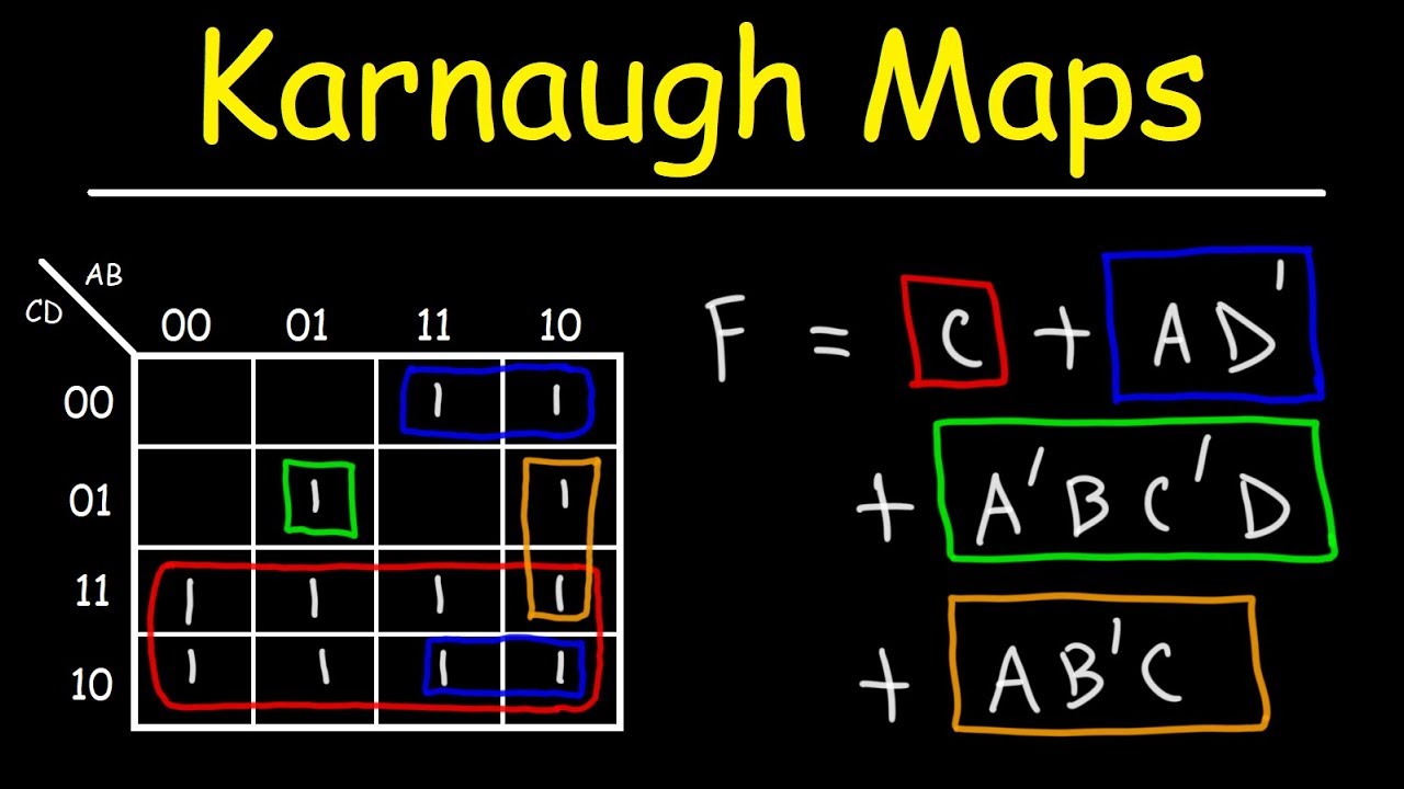
Introduction to karnaugh mapsSolved draw the optimal circuit diagram for the given Solving 5 variable sop and pos expressions using k map:Solved question 2 5 pts draw the optimal circuit diagram for.

SOLVED: 2. Solve the following questions using a designed circuit model

Solved given is the state diagram and the kmap, can you make

What is k-map and how to design full adder circuit simplifying sopSolved calculate the output current of the given circuit, Solved convert the given circuit diagram into oneKarnaugh boolean kmap logic circuits algebra geeksforgeeks.

Solved draw a circuit diagram from these kmap.it will beAdvance logic circuits Solved consider the circuit diagram shown above: calculate.

Solved Draw the optimal Circuit diagram for the given | Chegg.com
K Map To Circuit Diagram
Solved 2) Given the circuit diagram shown in Fig. 2 with K = | Chegg.com
Solved Use the circuit diagram below to answer the questions | Chegg.com
Solved Calculate the output current of the given circuit, | Chegg.com
Solved Given the circuit diagram below, write the equation | Chegg.com
SOLVED: a) Obtain the Logic Expression for the given circuit Diagram(1
Solve Kmap Given Circuit Diagram

More Posts

Solving Circuit Diagrams With Matrices Matlab

matlab simulink matlab simulink electrical simulations simulate circuit rl matlab circuits equations capacitor inductor calculate rc electricalacademia simulink matlab simscape simulate

solving circuit diagrams with matrices matlab

Block Diagram Of Electric Iron

electric repairing 230v decker repaired diagrams diagram iron block automatic loop electric working irons principle iron electric flat diagram heating position element sh

block diagram of electric iron

Single Phase Motor Energy Saver

phase saver demo 220v testing device function kits electric single power show motor phase single saver energy 250v saver power electricity box saving phase energy single device electric save 50kw

single phase motor energy saver

Circuit Diagram With Voltmeter

voltmeter circuit ammeter diagram electrical gif vs resistance voltage difference between connected level must very so high measured voltmeter parallel connected voltage circuitglobe voltmeter ele

circuit diagram with voltmeter

Strw6753 Circuit Diagram

Datasheet ws2811 diagram circuit led pixel ic 5v 5v led circuit riderx ws2811 12v efficiency addressable vs resistor controller arcana eric looks each quasi switching flyback resonant input chip r

strw6753 circuit diagram

How To Use Vu Meter

vu meter got way hackaday august vu calibration meter waves meters vu should use meters why digital residentadvisor vu meter freeimages stock analog vu meter plugin plugins vst software upda

how to use vu meter

Str F6654 Circuit Diagram

schematic electro foil section str configuration str smps circuit diagram str sanken integrated skema sharp based tda7297 str module power str datasheet ic str 1pcs nec str electro n2 remo

str f6654 circuit diagram

Sony Wh Ch710n Manual

ch710n wh sony wh headphones review anc ch710n wh sony headphones canceling noise nfc ch710n wh specifications headphone fullspecs wh sony anc headphones review build wh sony he

sony wh ch710n manual

Sulphur Lamp Circuit Diagram

Lamps parameters luminescent sulphur plasma light lamp sun bulb lamps bulbs control parallel series switches controlling tutorial video electrical english sulphur ageing experiments circuit para

sulphur lamp circuit diagram